We 
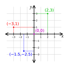
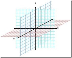
See, there are two schools of thought on this subject and unfortunately both make perfect sense. On one hand, one group views X,Y as already representing Left/Right and Up/Down on a computer display, so the most logical conclusion is that Z should represent depth. Imagine for a second if you could reach INTO your monitor… that would be the Z coordinates. If you have already done some 2D graphics work, X and Y are probably pretty well entrenched in your mind as representing screen position, so this probably makes a lot of sense to you. For the record, this type of coordinate system where Z represents depth is referred to as a Y-up as Y represents the up direction. Personally, this is the most intuitive to me.
But then there are these other types of people in the world… engineers and architects and to them X,Y are viewed in a much different context. See instead of thinking in terms of a computer monitor in front of them, they think in terms of blueprints on a table. With a system 
Now you may be asking yourself… how exactly does this affect me? Well, that’s an easy one… all kinds of tools work with a different axis set. Of the 3 we use, Wings 3D is Y-up, Blender is Z-UP and Unity 3D is Y-up. So… as you are creating your assets they spend a lot of time flipping around between programs!
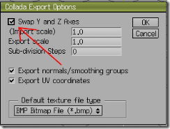
With Wings 3D, if going directly to Unity, you are in luck, no more work has to be done. Most of the time though, we will be going from Wings to Blender first. Fortunately this fix is pretty easy. When you export your model ( via the menu File->Export->Collada ), click the little box icon to bring up options. Then make sure you select “Swap Y and Z axis” checkbox as shown in the picture below, then OK and export. This setting is “sticky” so you should only have to choose it once.

Now in Blender things get a bit trickier and therefore it’s really easy. Frankly, there is nothing you can do. The axis system is fixed so you can’t change that, and there are no options when exporting. I suppose you could model everything rotated but that would add a great deal of confusion.
So that leads us to Unity, currently the importer (version 2.57b ) is working properly, so thankfully you *shouldn’t* have to do anything, it automatically rotates it for you. That said, this importer isn’t always the most… stable thing. In cases where it doesn’t import correctly, you have one of two options. First you can rotate manually 90 degrees about the X axis when you create an asset in Unity. Otherwise, you can perform the conversion as part of the import process by creating an AssetPostProcessor which is a script run during the importation process, allowing you to make last second alterations.
For the record, this isn’t only a Blender/Unity problem, Max, Maya and Softimage are all Z-Up modelers by default, while I believe Cinema 4D is Y-up. It is something to be aware of when moving from one application to the next. If it seems like your model is doing a backflip, the axis difference is most likely the cause.
